When designing projects for sheet metal fabrication, you need to make several design accommodations to ensure that any fasteners or cuts made near edges, bends, or other fasteners don’t distort your final product.
Below are a few places where distortions could occur and how to avoid them.
If you need help designing your next sheet metal product, give the team at Hansen Industries a call and they can help eliminate or minimize distortions in your design.
Close to the edge (single edge): When PEM hardware is installed too close to the edge, the sheet metal may bulge. To avoid this, special anvils are used to reinforce the edges. Keep in mind this design modification will require additional tooling cost.

Close to the edge (multi-sided): When a fastener is installed too close to a multi-sided edge, the metal could become distorted and reduce the holding power of the clinch feature. Edges should be supported during installation to avoid this.

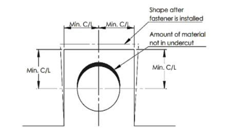
Near a bend: It’s best to bend the metal before installing PEM hardware near a bend. Avoid fasteners too close to adjacent flanges, and use the “centerline-to-edge” value from the diagram below to calculate distance to the outside of the bend radius.

Multiple fasteners: If your project includes multiple fasteners, use the formula C/L to edge +1/2 the diameter of the second mounting hole to avoid distortion of nearby holes.


